
Meera Satheesh
Building Construction 2 (ARC 2513)
Project 1: Skeletal Construction “A Shelter For One”
Skeletal Construction is basically a frame structure which is used to resist vertical forces (Gravity, Rain, Dead and Live Load) and Lateral Forces (Wind & Earthquakes).
In a group of 5, we were required to construct a shelter for 1 according to the following specifications;
a) Scale : Fit ONE person in sitting position (1:1).
Max height of 1.5m
Max base size of (0.75 x 0.75)m
b) Construction : Demonstration of the knowledge of skeletal frames and its joints.
Elevated 5 Inches off the ground
c) Joints : Reflection of actual joints
d) Materials : Recycled materials.
Relation to its function
e) Other Design Considerations : Light & Portable
Resistant to outdoor weather
Easy access in and out of shelther
SHOULD NOT BE OVERLY DESIGNED
f) Test : Withstand weight of 60kg up to 2 minutes.
g) Design analysis, construction progree and test results to be provided in A3 bound report.
h) Final report
Design & Construcion Progress
 Drawing process (Design) |  Drawing process (Design) |  Modelling Process (Design) |
|---|---|---|
 Modelling Process (Design) |  Modelling Process (Design) |  Design confirmation (Final Design) |
 Collection of materials |  Making the base |  Making the base |
 Making the base |  Making the base |  Making the base |
 Making the base |  Final base image |  Lap Joints |
 Lap Joints |  Support structure for base |  Support structure for base |
 Support structure for base |  Adding cardboards & egg crates |  Final image of platform |
 assembling the skeleton for shell |  Assembling shell structure (bottles) |  Assembling shell structure (bottles) |
 Assembling shell structure (bottles) |  Assembling shell structure (bottles) |  Final structure |
 Easy, Light & Portable |
Final Product
Testing Day
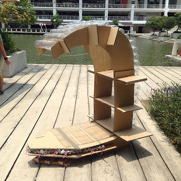

The structure managed to withstand more than 2 minutes of the weight of 3 grown guys which sums up to more than 60kg.
Final Report
Group Photo

Click the image above to proceed to report
Reflection
A few of the things that I've learnt during this project is that teamwork and communication is very important in completing any task. Through this project we as a group have understood the basis of skeletal structure and its relevant structural components. Besides that, we learnt that the allocation of work; in terms of collecting materials, construction of joints, base and the structure was crucial.
Through this allocation, we've learnt to work together and teach each other what others aren't that familiar with as everyone has their strengths and weakness.
I've also understood how a skeletal structure reacts under different types of loading. These understandings were clearly demonstrated by the construction, this allowed us to manipulate the construction based on our personal problems and designs.
One main problem that we faced during this process was miscommunication between members in which we managed to solve quickly and got back on track.
Project 2:Understanding Forces in Solid Structure and Surface Structure
Skeletal Construction is basically a frame structure which is used to resist vertical forces (Gravity, Rain, Dead and Live Load) and Lateral Forces (Wind & Earthquakes).
Solid Construction are basically structures that are normally solid all the way through, meaning that there are no holes or empty space in the construction. These structures can also hold a fair bit of weight and is normally pretty heavy it’s self.
Surface Construction is a structure system which defines a space and provides support simultaneously. The members are united as one homogeneous entity to form structure and space
In the group of 5 according to our previous group, we were required to propose 3 buildings that have a combination os skeletal, solid and surface construction. Upon this proposal, we were required to select a building using at least 2 DIFFERENT TYPES of structural system.
After some research, our group first proposed, The Guggenheim Museum Bilbao, Spain by Frank Ghery (Skeletal & Solid Construction), The Louis Vuitton Building by Frank Ghery (Surface & Skeletal Construction) and _______. Upon plenty of discussions, we decided to use The Guggeneheim Museum Bilbao by the very famous Frank Ghery. We were also required to build up the structure or a part of the buildign which clearly shows the 2 systems mounted on an A3 sie base.
The scale in which we decided to use was 1:200 for the mass model and 1:75 for the exposed model. Besides having to build the model, we were also required to immitate its materials or choose materials which falls closest to the actual material.
Our processes were needed to be compiled into an A4 size booklet which contains;
a) A brief introduction of the building
b) Related drawings like perspective, plan and sections where the model
c) Construction method as detailing of different parts of the buildings
d) Describe each structural system identified in terms of Function, Material, Joints and Load distribution. Students are encouraged to use annotated sketches / diagrams for explanation.
e) Modelling process documentation using photographs.
Besides this group work, we were also required to produce a 2D detailed drawing (Isometric, Section) to show different parts of the selected buildings complete with annotations and specifications to show our personal understadings on how the building is built.
Design & Construcion Progress
 Cardboard Temlpate was made |  Cardboard Temlpate was made |  Cardboard Temlpate was made |
|---|---|---|
 Cardboard Temlpate was made |  Cardboard Temlpate was made |  The plaster was mixed |
 The plaster was mixed |  Plaster is poured into the template and left to dry overnight |  Mould is taken out from the template |
 Mould is taken out from the template |  Mould is taken out from the template |  Problem occured when taking out the mould too early |
 Scaring done on aluminium sheet (Titanium cladding) |  Scaring done on aluminium sheet (Titanium cladding) |  Sheets are glued to the mass models |
 Sheets are glued to the mass models |  Sheets are glued to the mass models |  Scaring done on balsa wood and glued on (Stone cladding) |
 Railings were added on |  Plastic sheets were cut (curtain walling) |  plastics were glued to crete curtain walls |
 Mullions were added |  Mullions were added |  Mullions were added |
 Strips for the trusses were then cut |  Trusses were then spray painted |  Finished trusses and mass models |
 Strips were cut and glued for the Skeletal structure |  Strips were cut and glued for the Skeletal structure |  Strips were cut and glued for the Skeletal structure |
 Strips were cut and glued for the Skeletal structure |  Detailed Connection for skeletal structure |  Detailed Connection for skeletal structure |
 Detailed Connection for skeletal structure |  Detailed Connection for skeletal structure |  The skelatal structure was spray painted |
 The skelatal structure was spray painted |  The skelatal structure was spray painted |  The skelatal structure was spray painted |
 The skelatal structure was spray painted |  The skelatal structure was spray painted |  The skelatal structure was spray painted |
 The skelatal structure was spray painted |  The skelatal structure was spray painted |  The skelatal structure was assembeled |
 Parts for the joint model was cut |  Parts for the joint model was cut |  Parts for the joint model was cut |
 Parts for the joint model was cut |  Parts for the joint model was cut |  Parts for the joint model was glued together |
 Parts for the joint model was spray painted |  Template for the solid floor was cut |  Wire mesh was cut to be placed on the template before plaster was poured to act as the reinforcement. |
Final Product

Individual 2D Detailed Drawing
Click the image above to proceed to file
Group Photo

Final Report
Click the image above to proceed to report
Reflection
A few of the things that I've learnt during this project is that teamwork and communication is very important in completing any task. Through this project we as a group have understood the basis of the skeletal and solid construction and its relevant structural components used for these systems. Besides that, we learnt that the allocation of work; in terms of collecting materials, making the mass model, titanium and stone cladding, curtain wallings, the detailings and the structure was crucial.
Through this allocation, we've learnt to work together and teach each other what others aren't that familiar with as everyone has their strengths and weakness.
I've also understood how to indentify the basic structural systems used in a particular construction. Furthermore, it gave us a clear picture on how to differenciate skeletal, solid and surface construction systems in terms of loads and forces which are acting on the structural elements.
A good recognision and application of these construction knowedge is needed to create a good design. Through this, we automatically were needed to analyse the issues of strength, stiffness and stability of the structures including modes of structural systems, forces, stress and strain and the laws of static.
One main problem that we faced during this process was miscommunication between members in which we managed to solve quickly and got back on track.